RADIO TRANSMITTER (TX)
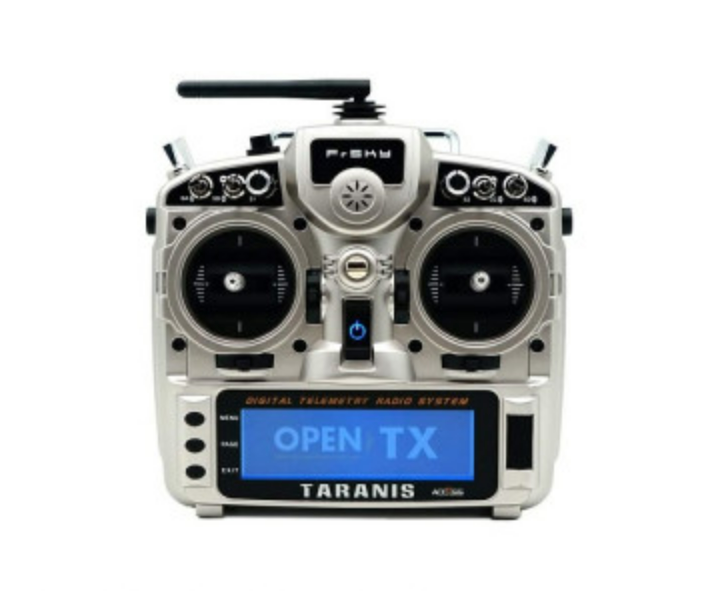
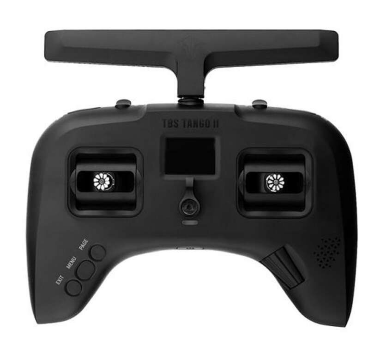
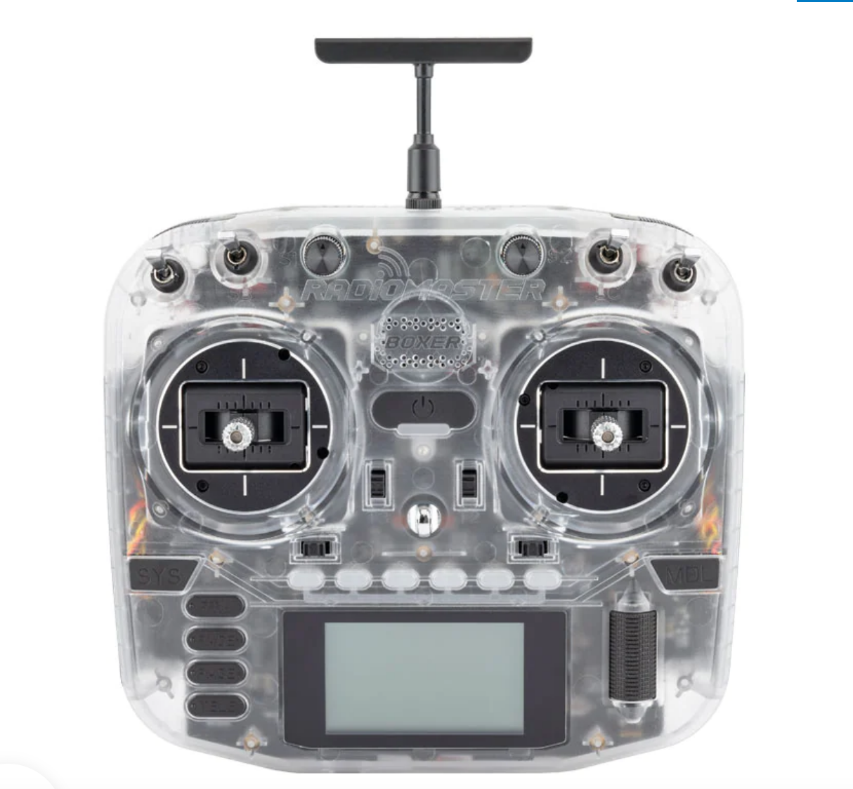
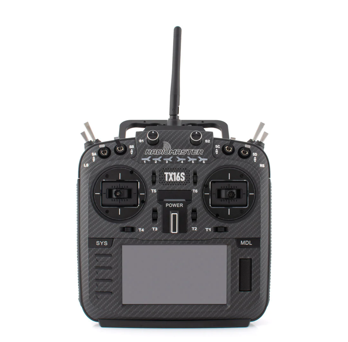
A radio transmitter is a handheld device essential for controlling FPV drones. It sends signals to the drone’s receiver, interpreting commands through the flight controller for precise movement. A reliable, high-quality transmitter is crucial for swift and accurate drone response. Key features include comfortable grip, responsive sticks, and advanced options like customizable settings and telemetry data, offering pilots a tailored and enjoyable flying experience.
Mode
Radio mode determines the configuration of the two control sticks on a radio transmitter, with four options available: Mode 1, Mode 2, Mode 3, and Mode 4. Among these, Mode 2 is the most commonly used configuration.

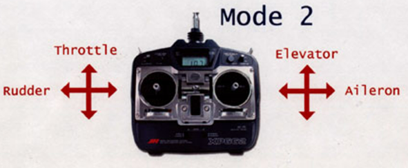


Gimbal Types
There are two main types of gimbals: Potentiometer and Hall Sensor
- Potentiometer-based gimbals are more budget-friendly but tend to wear out faster. This is because they rely on physical contacts and brush joints, leading to friction over time.
- Hall Sensor gimbals utilize magnets to determine the stick position, making them more durable in the long run
External transmitter modules
In today’s radio transmitters, there’s commonly an option to attach an external transmitter module. This enables users to use a different frequency, like 900MHz in a 2.4GHz radio, or utilize a receiver from another brand/protocol, such as the Crossfire CRSF module with a Crossfire V2 Micro Receiver in a FrSky Taranis. This flexibility greatly enhances compatibility and customization based on specific preferences or equipment choices.


Transmitter firmware
Transmitter firmware is similar to the operating system or software of a radio controller.It provides the interface for creating and modifying drone profiles, establishing connections with receivers, and configuring various controls. While manufacturers often install proprietary firmware, many enthusiasts opt for open-source alternatives like OpenTX, offering enhanced customization and advanced features Most commonly used firmwares are open tx ,Edge tx ,Frsky ,Flysky etc
Transmitter Protocols
Transmitter Protocols refer to the communication language employed by a controller to interact with its synchronized receiver. This language is brand-dependent, necessitating controllers and receivers from the same manufacturer for successful pairing. However, cross-brand compatibility can be achieved through the use of external modules. Prominent protocols commonly utilized include CRSF, ELRS, IBUS, DSM, among others.
RADIO RECEIVER (RX)
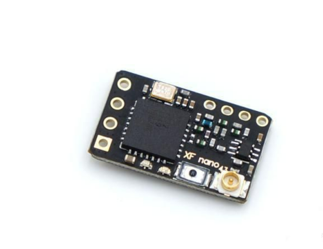
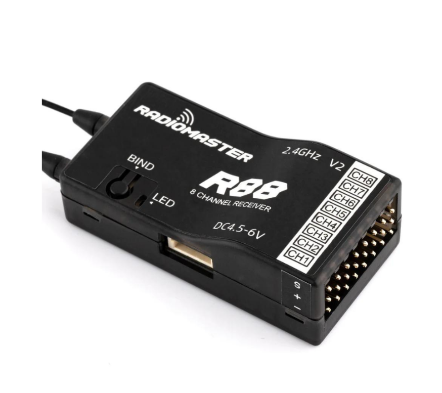
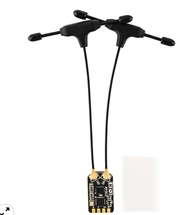
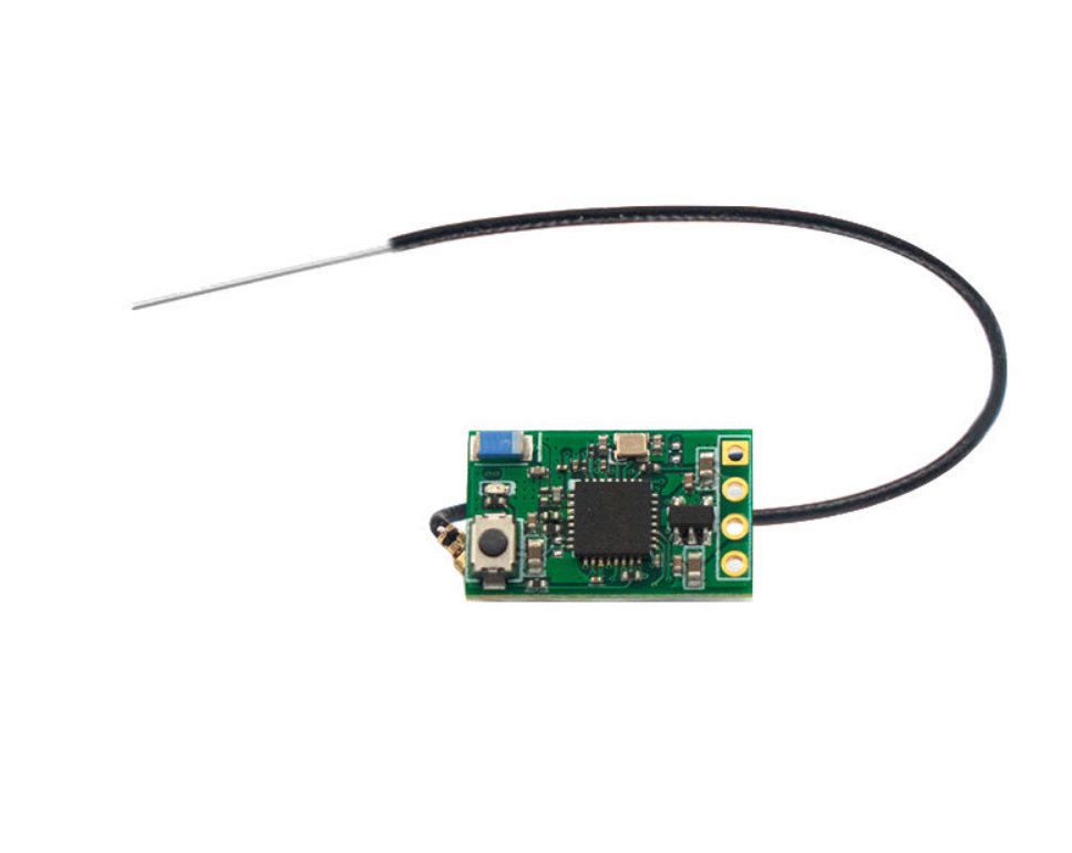
A radio receiver is a device that captures and decodes radio signals transmitted by the radio transmitter on the FPV drone. It plays a crucial role in converting these signals into commands that the flight controller can interpret, allowing for precise control of the drone’s movements. The receiver acts as a communication bridge between the pilot’s transmitter and the drone’s flight controller, facilitating real-time control during flight.
Receiver protocol
A receiver protocol refers to the communication language or standard used between the radio receiver (RX) and the flight controller (FC). It dictates how the receiver transmits information to the flight controller, enabling the translation of radio signals into commands that the FC can understand. Common receiver protocols include SBUS, DSM, IBUS, CRSF, etc. each with its own set of specifications for transmitting data between the receiver and the flight controller.
Channels
In the context of radio control systems, a channel refers to a dedicated communication pathway that facilitates the transmission of specific information between a radio transmitter and receiver. Each channel is assigned to a particular control input, such as throttle, yaw, pitch, and roll in the case of an FPV drone.A minimum of four channels is needed for essential inputs, with additional channels for toggle switches.
Telemetry
Telemetry refers to the data transmitted from the Radio Receiver back to the Radio Transmitter. This data typically includes various information depending on the type of radio and flight controller. Key pieces of information include battery voltage readings, current draw, and “RSSI” (Radio Signal Strength Indication). Telemetry data can be viewed on the telemetry screen in OpenTX and can also be customized to trigger audio warnings.
FREQUENCY (f)
Frequency refers to the number of complete cycles of a periodic waveform that occur in a unit of time, usually measured in Hertz (Hz)
Wavelength (λ):
Wavelength is the distance between two successive points in a wave with the same phase. In simple terms, it’s the length of one cycle.
The relationship between frequency (f) and wavelength (λ) is given by the formula:
c =f λ, where c is the speed of light.
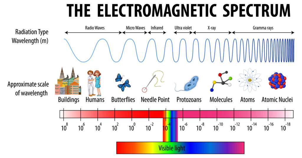

In general terms, there is an inverse relationship between frequency and wavelength. As frequency decreases, wavelength increases, and vice versa.
1.Lower Frequency (Longer Wavelength):
1.Pros: Longer wavelengths, associated with lower frequencies (e.g., 900MHz), can better penetrate obstacles like buildings and vegetation. They also exhibit better performance in non-line-of-sight conditions.
2.Cons: These frequencies may require larger antennas, and the equipment can be bulkier.
2.Higher Frequency (Shorter Wavelength):
1.Pros: Shorter wavelengths, associated with higher frequencies (e.g., 2.4GHz, 5.8GHz), allow for more data transmission capacity and are suitable for short-range, line-of-sight applications.
2.Cons: Signal penetration through obstacles may be reduced.

